


History of the 24” at TDS Observatory
All of the major components of the 24” telescope were custom designed and built. The original goal was to build a telescope capable of producing high quality wide field images. This requires attention not only in the design of the optical system but also a telescope mount capable of stable and precise tracking.
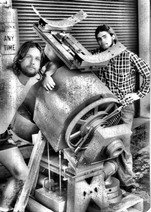 The German equatorial telescope mount was originally built by SDSU staff in the ‘60s(?) and primarily used by SDSU students for photometry projects using a photoelectric photometer. After obtaining the mount via an SDSU surplus equipment sale in the early ‘80s (see photo), it was determined that for long exposure imaging applications significant improvements were needed, primarily in the telescope’s drive system. Over the years as funding and creativity became available, issues with the mount were fixed and capabilities upgraded. Bob Harwell took the lead in designing upgrades to the mount system that included spring mounting the worm drives for both the RA and DEC axes, and adding stepper motor control that enabled a computer interface with GoTo like operation. When it was observed that the original stepper motors introduced high frequency oscillation, 50:1 harmonic gear heads were added that reduced the oscillation to undetectable levels. When even greater pointing and tracking precision were desired, Bob Harwell again took the lead, replacing the stepper motors with brushless DC servo motors as well as adding optical encoder feedback to each axis. Computer control was upgraded from an obsolete DOS based system to a SiTech controller.
The optical tube assembly (OTA) for the 24” is a sturdy, open rectangular truss designed in the early ‘80s by Mike Hoffert and William Hodges. At close to 800 lbs., the goal was to eliminate flexure from the relatively large (and heavy) 12” secondary mirror. Fortunately the mount is big enough to support this kind of load. Mike Hoffert designed the original 24” mirror cell which had some upgrades added by Sina Sadjadi who also did the upgrade of adding a computer controlled secondary focuser that enables static mounting of focal plane sensors (e.g. CCD cameras).
A Ritchey-

160 VDC and IT”S ALIVE! Click on the icon to see a thrilling (mpg) video of the RA clutch in action for the first time in thirty years!

Music of the gears. Click on the icon to listen to the original TDS 24” stepper RA motor.